| 일 | 월 | 화 | 수 | 목 | 금 | 토 |
|---|---|---|---|---|---|---|
| 1 | 2 | 3 | ||||
| 4 | 5 | 6 | 7 | 8 | 9 | 10 |
| 11 | 12 | 13 | 14 | 15 | 16 | 17 |
| 18 | 19 | 20 | 21 | 22 | 23 | 24 |
| 25 | 26 | 27 | 28 | 29 | 30 | 31 |
- scattering
- ue4
- GPU
- SGPR
- unrealengine
- scalar
- forward
- Nanite
- hzb
- shader
- Graphics
- RayTracing
- Study
- optimization
- SIMD
- rendering
- texture
- vulkan
- ShadowMap
- wave
- Shadow
- UE5
- VGPR
- DirectX12
- deferred
- atmospheric
- 번역
- DX12
- GPU Driven Rendering
- Wavefront
- Today
- Total
RenderLog
PathTracing (1/2) 본문
PathTracing(1/2)
최초 작성 : 2024-03-01
마지막 수정 : 2024-03-01
최재호
목차
1. 목표
2. 내용
3. 구현 결과
3.1. Cornell box orig scene
3.2. Cornell box sphere scene
3.3. Hyperion sphere light scene
3.4. Hyperion rect lights scene
4. 실제 구현 코드
5. 레퍼런스
1. 목표
다양한 BSDF 를 평가해보고 변형해볼 수 있는 테스트 베드를 위한 PathTracer 를 제작합니다.
이 글은 총 2개로 나뉘며, 첫 번째는 PathTracing 의 구현 기반을 마련하는 것을 목표로 합니다. 두 번째 글은 다양한 BSDF 를 도입하여 여러 가지 재질을 표현하는 것을 목표로 할 예정입니다.
사전지식
- DXR or VkRaytracing 에 대한 이해
- PBR 에 대한 이해 ([UE4 PBR] Split sum appoximation 리뷰 참고)
- Radiometric Quantities 에 대한 이해
구현은 DirectX12 DXR, Vulkan VkRaytracing 을 사용하여 구현하며, 구현에 사용한 그래픽카드는 RTX3070 입니다.
2. 내용
PathTracer 에 사용할 Scene 은 레퍼런스1 에서 활용하고 있는 Scene 을 그대로 활용했습니다. 여러 Scene 중 이번에 사용할 Scene 은 Cornell box 와 Disney 의 hyperion scene 입니다.
이번 글에서는 아래 내용을 다룹니다.
- 기본적인 Lambertian BRDF 와 Microfacet Specular BRDF 를 사용 (이 부분은 [UE4 PBR] Split sum appoximation 리뷰 참고)
- PathTrace 를 통한 Radiance 계산 식
- Glass sphere 의 Transmittance 기본 처리 (굴절만 하며, 100% 투과로 가정하고 사용함)
먼저 PathTracing 에 대해서 알아봅시다. PathTracing 은 눈에서부터 광원까지의 경로를 추척해가며 최종적으로 눈으로 들어오는 Radiance 를 평가합니다. Radiance 를 평가하는 동안 다양한 재질을 거쳐서 광원으로 이동하게 되며, 이 재질들은 각각의 특성에 따라서 빛을 특정 범위로 산란시킬 것입니다. 아래 그림1을 봐주세요. 그림1은 여러 산란 경로 중 하나를 보여줍니다. 눈과 광원인 P0, P3 를 제외한 P1, P2 에서는 재질에 따른 산란이 발생합니다. 리얼타임 렌더링에서 한 프레임에 이 수많은 경로를 모두 평가할 수 없기 때문에 PathTracing 에서는 경로에 대한 평가들을 매프레임 계속 누적합니다.
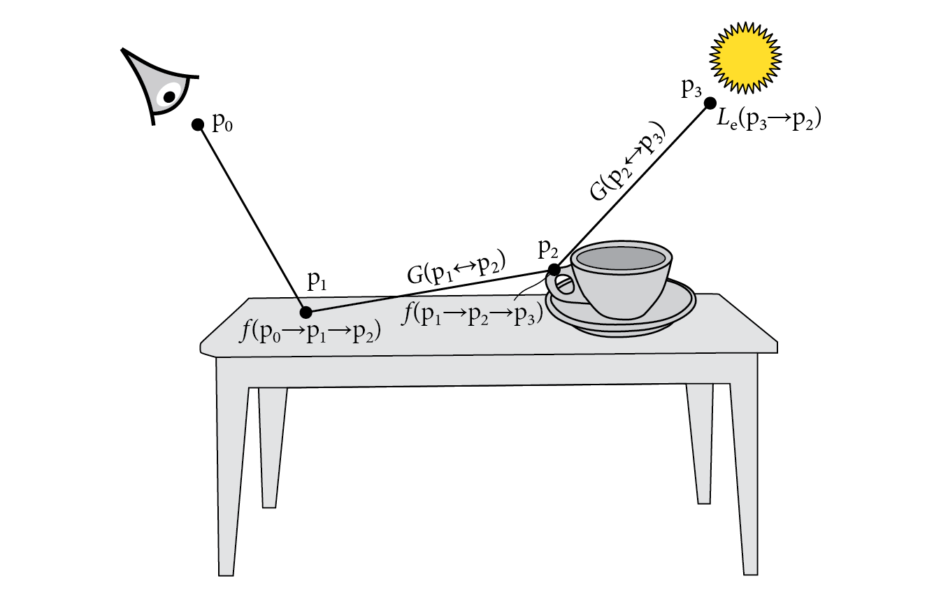
눈으로 입사하는 Radiancce 를 평가하기 위해서 우리는 Light Transport Equation 을 사용합니다. 그림2 의 식을 참고해 주세요.
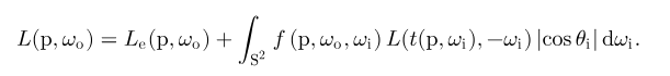
P1 점에서 P0(눈) 으로 들어오는 Radiance 를 계산하기 위해서는 P2, P3 에서 들어오는 Radiance 정보 또한 모두 모아야 합니다. 그림3 은 거기에 대한 식을 보여줍니다.
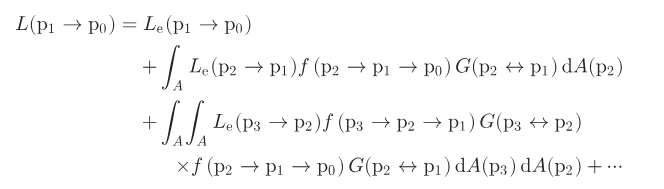
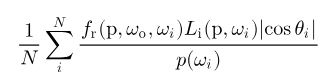
실제로는 적분시 Monte Carlo 방식을 사용하기 때문에 적분식 내에 있는 식은 그림4 의 식으로 대체될 것입니다.
이 식을 코드로 나타내면 아래와 같이 나타낼 수 있습니다. 실제 손으로 P0~P3 의 지점에 적절한 데이터를 넣고 계산해 보면, 여러 프레임 동안 얻은 PathTracing 결과를 중첩 시 그림3과 같이 식이 된다는 것을 알 수 있습니다. (아래 코드는 레퍼런스1, 2 를 참고하였습니다)
// reygen shader
while (payload.RecursionDepth < MAX_RECURSION_DEPTH)
{
    // Called TraceRay.. and then evaluate below code
    // payload.Radiance += material.emission;
    // payload.Attenuation = BRDF_Cos / SamplePDF;
    /////////

    //
    radiance += attenuation * payload.Radiance;
    attenuation = max(0, attenuation * payload.Attenuation);
    ...
}
P0~P3 지점까지 재귀적으로 Path 를 타고 들어가게 되는데 이 부분은 while 을 사용하여 들어갈 수 있는 최대 재귀 Depth 를 제한합니다. TraceRay 를 호출을 완료할 때마다 ClosestHit 으로 부터 얻어오는 payload 에서 다음 Ray 에 대한 정보를 얻고 계속해서 해당 Ray 를 반사합니다. 아래 코드를 확인해 주세요.
while (payload.RecursionDepth < MAX_RECURSION_DEPTH)
{
    if (payload.IsRayPenetratingInstance()) // for glass sphere transmittance
        TraceRay(Scene, RAY_FLAG_CULL_FRONT_FACING_TRIANGLES, ~0, 0, 0, 0, ray, payload);
    else
        TraceRay(Scene, RAY_FLAG_CULL_BACK_FACING_TRIANGLES, ~0, 0, 0, 0, ray, payload);

    radiance += attenuation * payload.Radiance;
    attenuation = max(0, attenuation * payload.Attenuation);

    ray.Origin = payload.HitPos;
    ray.Direction = payload.HitReflectDir;
    ++payload.RecursionDepth;
}
RayTracer 를 만들면서 한 가지 고민되었던 점은 Glass 타입의 재질의 경우 투과를 고려해야 된다는 점입니다. 투과가 되는 경우 매질이 달라지기 때문에 굴절율이 생기고 매질이 달라지는 지점에서 빛의 경로를 굴절 시켜줘야 합니다. DXR, VkRayTracing 의 경우 TraceRay 를 사용할 때 RAY_FLAG_CULL_BACK_FACING_TRIANGLES와 RAY_FLAG_CULL_FRONT_FACING_TRIANGLES 를 사용하여 충돌할 삼각형의 감기 방향을 고려할 수 있습니다. 그래서 Glass 재질 타입을 전면에서 부딧치는 경우 payload 에 PenetratingInstnace 플래그를 활성화해주고, Penetrating 상태면, 삼각형의 후면과 충돌할 수 있도록 변경하여 물체 안을 뚫고 지나갈 수 있도록 구현했습니다. 위의 코드에서 해당 내용을 확인할 수 있습니다.
그리고 아래코드는 Glass material 의 BSDF 에 대한 코드입니다. 굴절을 해야 하는 경우 투과가 진행됩니다. 여기서 Normal 과 View 방향이 같은 경우 Glass material 에 진입, 그 반대의 경우 탈출의 경우로 판정하고 Penetrating 정보를 설정/해제하는 것을 볼 수 있습니다. 그리고 이 정보에 따라서 TraceRay 호출 시 Facing 방향을 조정합니다.
Glass material 은 현재 Radiance 가 흡수, 산란이 없는 100% 투과로 구현되어 있습니다. 이 부분은 다음글에서 BSDF 를 본격적으로 다루면서 수정할 예정입니다.
void SamplingBRDF(out float3 SampleDir, out float SamplePDF, out float3 BRDF_Cos
, in float3 WorldNormal, in float3 WorldFaceNormal, in float3 SurfaceToView, in MaterialUniformBuffer mat, inout RayPayload payload)
{
...
else if (r3 < cdf[3]) // glassPart
{
...
    if (Random_0_1(payload.seed) < F && NoV > 0)
    {
        SamplePDF = 1;
        BRDF_Cos = 1;
        SampleDir = reflect(-SurfaceToView, WorldHalf);
    }
    else
    {
        SamplePDF = 1;
        BRDF_Cos = 1;
        SampleDir = refract(-SurfaceToView, WorldHalf, eta);

        if (NoV > 0) // In glass material
        {
            payload.SetPenetratingInstnaceIndex(InstanceIndex());
        }
        else // Out from glass material
        {
            payload.ResetPenetratingInstanceIndex();
        }
    }
    cosine_theta = 1.0f;
}
...
}
PathTracer 의 SamplingBSDF 의 나머지 두 파트인 Diffuse, Specular 파트는 레퍼런스4 의 UE5 PBR 에 있는 식을 기반으로 사용했습니다. Specular BRDF 에서는 Anisotropy 가 적용되지 않았는데, 다음글에서 해당내용을 개선하면 좋을 것 같습니다. 아래 코드를 참고해 주세요.
void SamplingBRDF(out float3 SampleDir, out float SamplePDF, out float3 BRDF_Cos
, in float3 WorldNormal, in float3 WorldFaceNormal, in float3 SurfaceToView, in MaterialUniformBuffer mat, inout RayPayload payload)
{
...
float r3 = Random_0_1(payload.seed);
if (r3 < cdf[0]) // diffusePart
{
    // Lambertian surface
    SampleDir = CosWeightedSampleHemisphere(payload.seed);
    cosine_theta = SampleDir.z;
    SampleDir = ToWorld(WorldNormal, SampleDir);

    if (diffusePart > 0.0f)
    {
        if (cosine_theta < 0)
        {
        // Underneath skip.
        }
        else
        {
            float3 BRDF = INV_PI * mat.baseColor;
            BRDF_Cos += BRDF * diffusePart;
            SamplePDF += (INV_PI * cosine_theta) * diffuseWeight;
        }
    }
}
else if (r3 < cdf[1]) // specularPart
{
    // Cook torrance brdf from https://cdn2.unrealengine.com/Resources/files/2013SiggraphPresentationsNotes-26915738.pdf
    float r1 = Random_0_1(payload.seed);
    float r2 = Random_0_1(payload.seed);
    WorldHalf = normalize(ImportanceSampleGGX(float2(r1, r2), mat.roughness, WorldNormal));
    SampleDir = reflect(-SurfaceToView, WorldHalf);
    cosine_theta = saturate(dot(WorldNormal, SampleDir));

    if (specularPart > 0.0f)
    {
        float NoV = saturate(dot(WorldNormal, SurfaceToView));
        float NoL = saturate(dot(WorldNormal, SampleDir));
        float NoH = saturate(dot(WorldNormal, WorldHalf));
        float VoH = saturate(dot(SurfaceToView, WorldHalf));

        if (cosine_theta < 0)
        {
        // Underneath skip.
        }
        else
        {
            float3 F0 = mat.baseColor;

            float D = DistributionGGX(WorldNormal, WorldHalf, mat.roughness);
            float G = GeometrySmith(mat.roughness, NoV, NoL);
            float3 F = FresnelSchlick(cosine_theta, F0);
            float3 BRDF = F * (D * G / (4 * NoL * NoV));

            BRDF_Cos += BRDF * specularPart;
            SamplePDF += (D * NoH / (4 * VoH)) * specularWeight;
        }
    }
}
...
}
구현에 대한 내용은 여기까지입니다. 다음글에서는 이 PathTracer 를 기반으로 다양한 BSDF 를 평가해 보겠습니다.
3. 구현 결과
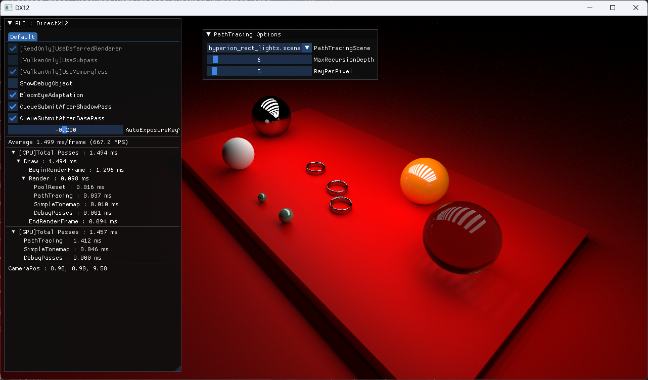
3.1. Cornell box orig scene
3.2. Cornell box sphere scene

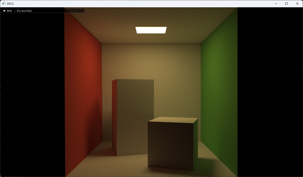
3.3. Hyperion sphere light scene
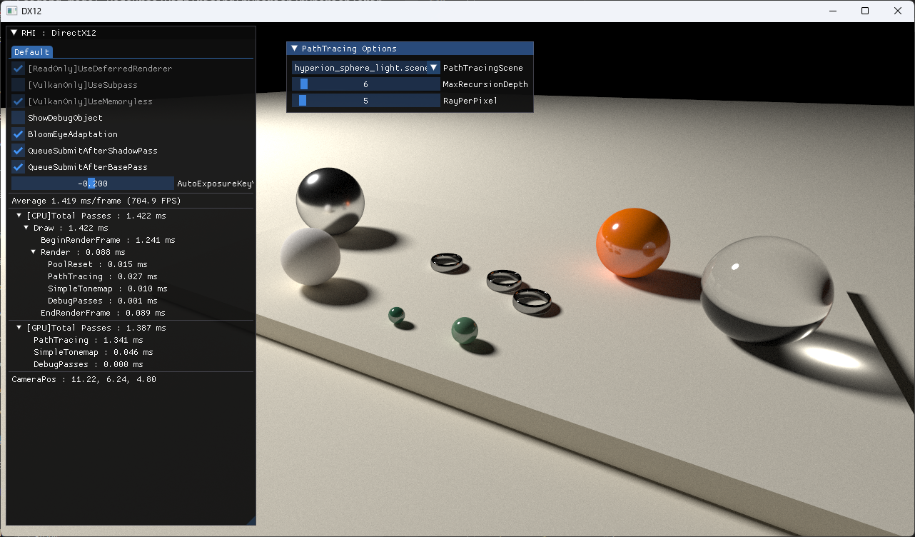
3.4. Hyperion rect lights scene
4. 실제 구현 코드
https://github.com/scahp/jEngine/tree/PathTracingBasis
5. 레퍼런스
1. https://github.com/knightcrawler25/GLSL-PathTracer
2. https://github.com/phgphg777/DXR-PathTracer
3. https://pbr-book.org/4ed/contents
4. https://scahp.tistory.com/96
5. https://pbr-book.org/4ed/Light_Transport_I_Surface_Reflection/Path_Tracing
6. https://scahp.tistory.com/53
7. https://pbr-book.org/3ed-2018/Light_Transport_I_Surface_Reflection/The_Light_Transport_Equation
'Graphics > Graphics' 카테고리의 다른 글
| AsyncCompute - DX12, Vulkan (0) | 2024.02.13 |
|---|---|
| RayTraced Ambient Occlusion(RTAO) (0) | 2024.01.31 |
| Bindless Resource - DX12, Vulkan (0) | 2024.01.17 |
| DX12 Shader Visible Descriptor Heap (0) | 2023.08.05 |
| BCn Texture Compression Formats 정리 (0) | 2023.04.21 |


