| 일 | 월 | 화 | 수 | 목 | 금 | 토 |
|---|---|---|---|---|---|---|
| 1 | 2 | 3 | ||||
| 4 | 5 | 6 | 7 | 8 | 9 | 10 |
| 11 | 12 | 13 | 14 | 15 | 16 | 17 |
| 18 | 19 | 20 | 21 | 22 | 23 | 24 |
| 25 | 26 | 27 | 28 | 29 | 30 | 31 |
- scattering
- rendering
- Study
- ShadowMap
- GPU
- unrealengine
- DX12
- Nanite
- UE5
- SIMD
- Shadow
- DirectX12
- VGPR
- forward
- Graphics
- hzb
- vulkan
- optimization
- ue4
- texture
- 번역
- wave
- SGPR
- atmospheric
- scalar
- Wavefront
- shader
- deferred
- GPU Driven Rendering
- RayTracing
- Today
- Total
RenderLog
[번역] Screen Space Reflections : Implementation and optimization – Part 1 본문
[번역] Screen Space Reflections : Implementation and optimization – Part 1
scahp 2021. 1. 28. 01:00개인 공부용으로 번역한 거라 잘못 번역된 내용이 있을 수 있습니다.
또한 원작자의 동의 없이 올려서 언제든 글이 내려갈 수 있습니다.
출처 : sugulee.wordpress.com/2021/01/16/performance-optimizations-for-screen-space-reflections-technique-part-1-linear-tracing-method/
Screen Space Reflections : Implementation and optimization – Part 1 : Linear Tracing Method
Posted on January 16, 2021 by Sugu Lee
1. Overview
Screen space reflections(SSR)은 표면에서 반사효과를 만드는 실시간 렌더링 기술입니다. 이 기술은 많은 시간동안 여러 게임에서 사용되어진 인기있는 기술중 하나입니다. 무엇이 이 기술이 인기있도록 해줄까요? 첫째로, 많은 게임의 기본 라이팅 파이프라인인 디퍼드 렌더링 파이프라인과 잘 맞습니다. 둘째로, 구현이 게임 시스템의 다른 요소와 직교(Orthogonal) 합니다. 이 효과가 기존의 렌더링 시스템의 다른 컴포넌트를 깨지 않고 추가할 수 있다는 의미입니다. 셋째로, 구현이 완전 쉽고(특히 linear tracing) 코드의 양이 적지만 이 효과가 화면에 보여질 때는 굉장히 인상적입니다
이 기술은 몇가지 결함이 있습니다. Scene Depth buffer를 World Geometry의 근사하는데 사용하기 때문에, 이 기술은 완벽한 반사효과를 만들 수 없습니다. 화면 바깥이나 혹은 다른 오브젝에 의해 가려지거나 반투명 오브젝트는 이 기술에 의해 캡쳐되지 않을 것입니다. 왜냐하면 그들은 Scene depth buffer에 있지 않기 때문입니다. 이런 한계에서 만들어진 artifacts를 어느정도 완화하는 몇가지 방법이 있습니다. 그러나 나는 이 글에서 다루지는 않을 것입니다.
대신에, 이 기술의 성능 최적화에 초점을 둘 것입니다. 비디오 게임에 사용되어진 렌더링 기술처럼, 가능하면 빠르고 효과적으로 동작하는 것이 중요합니다.
이 글에서는, OS-X에서 동작하는 간단한 어플리케이션을 만들기 위해 렌더링 API로 Apple의 Metal을 사용할 것입니다. 그러나 나는 여기에서 적용된 최적화가 다른 현대 렌더링 API에도 적용될 수 있다고 자신합니다.
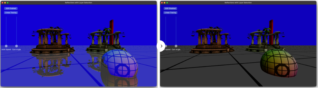
샘플 어플리케이션에서, Temple과 Sphere 모델이 바닥에 생성됩니다. SSR은 바닥과 Sphere에 적용됩니다. 그것은 반사되는 반직선을 화면 가장자리까지 추척합니다. 아래의 이미지는 이 글에서 설명하는 구현으로 SSR이 활성화(왼쪽)되었을 때와 비활성화(오른쪽)일때 어떻게 보여지는지를 보여줍니다.
2. SSR in a nut shell
최적화 파트에 깊게 들어가기 전에, 간단히 SSR의 구현에 대해서 설명하려고 합니다.
SSR은 아래 그림처럼 일부 픽셀의 반사 픽셀이 Scene color 텍스쳐에 있다는 점을 기반으로 합니다.

반사되어진 반직선을 계산하기 위해서 Depth와 Normal 방향을 사용합니다. 그리고나서, 화면공간에서 반직선이 Geometry와 충돌할 때까지 추적합니다. 반직선이 Geometry와 충돌한 곳은 픽셀이 반사되어질 위치입니다. 그 픽셀 컬러를 원본 픽셀 컬러에 더해줘서, 반사효과를 만듭니다.
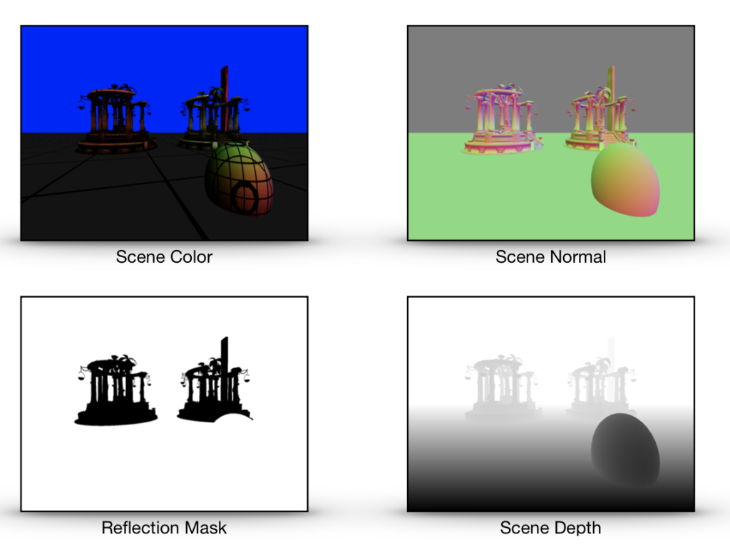
SSR은 화면에서 각 픽셀에 대해 4가지 정보를 요구합니다. 이것들은 Scene Normal 방향, Scene Depth, Scene Color 그리고 Reflection mask 입니다. (Normal 방향은 반사벡터를 구하기 위해서입니다. Scene depth는 픽셀의 3D 위치를 계산하기 위해서입니다. Scene color는 반사 컬러를 얻는데 사용됩니다. Reflection mask는 비반사 픽셀이 SSR을 무시하도록 하기 위해서 반사할지 말지에 대한 것을 저장합니다.)
디퍼드 라이팅 파이프라인을 사용할 때, 이 4개의 텍스쳐는 G-buffer 패스(Scene Normal, Scene Depth, Reflection Mask)와 라이팅 패스(Scene Color)에서 생성됩니다. 그래서 SSR과 디퍼드 라이팅 파이프라인에 통합할 때 이런 텍스쳐들을 생성하는데 추가비용이 들지 않습니다. 이것은 또한 G-buffer 패스와 라이팅 패스는 SSR 패스가 시작되기전에 반드시 끝나있어야 한다는 의미입니다.
포워드 라이팅 파이프라인의 경우, Scene color 텍스쳐와 Scene epth 텍스쳐는 메인 렌더링 패스 부분에서 생성됩니다. 그러나 Scene normal 텍스쳐와 Reflection mask에는 추가 패스가 필요하며 이것은 추가 비용이 됩니다.
Normal vector와 Reflection mask를 분리된 텍스쳐가 아닌 같은 텍스쳐에 저장하는 것도 가능합니다. 왜냐하면 Normal vector는 3개의 컴포넌트 Reflection mask는 1개의 컴포넌트가 필요하기 때문에 4개의 컴포넌트를 가진 단일 텍스쳐에 잘 맞습니다. 그리고 이것이 샘플 어플리케이션에서 작동하는 방식입니다.
3. The pseudo code
SSR 패스는 컴퓨터 쉐이더 커널에서 실행되어집니다. 아래는 수도코드입니다.
=Inputs : tex_sceneColor, tex_sceneDepth, tex_sceneNormalAndReflMask, sceneInfo, tid
// tex_sceneColor : color for each pixel
// tex_sceneDepth : depth in clip space for each pixel
// tex_sceneNormalAndReflMask : normal in world space, reflection mask (0:non-reflective, 1:reflective)
// tid : the thread position in grid. This is equivalent to the pixel position in the screen.
// sceneInfo is a structure contains information below
	// ViewSize : (width, height)
	// ViewMat : view transform matrix
	// ProjMat : projection matrix
	// InvProjMat : inverse projection matrix
Outputs : tex_outcolor

1. Get the normal and the reflection mask from 'tex_sceneNormalAndReflMask'
2. if reflection mask is not 0,
	3. Compute the position, the reflection vector, the max trace distance for the current sample in texture space.
	4. if the reflection vector is moving away from the camera
		5. Find the intersection between the reflection ray and the scene geometry by tracing the ray.
		6. If intersected
			7. Compute the reflection color by sampling the scene color texture at the intersection.
8. Add the reflection color to the color of the current sample to create the final color
4. The bottleneck
병목을 찾는 것은 어떤 것을 최적화하는데 첫번째 단계여야 합니다. 화면공간 반사의 경우, GPU 시간의 대부분을 보내는 곳은 반직선이 화면에서 Geometry(Scene depth buffer로 근사되어진)와 충돌하는 위치를 찾기 위해서 Reflection 반직선을 추적하는 부분입니다. 이것은 위의 수도코드에서 5번째 단계입니다.
그러므로, 추적 부분에서 효과적일 수 있는 최적화 기술을 소개할 것입니다.
5. The Linear Tracing Method
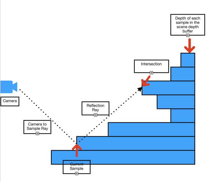
화면공간에서 반직선을 추적하기 위한 가장 간단한 접근방법은 Linear tracing입니다. 어떻게 작동하는 것일까요? 이름 처럼, 우리는 원점(Origin)으로 부터 반직선을 추적합니다. 매 단계마다 선형적으로 Depth 텍스쳐에서 반적선의 방향으로 다음 샘플로 옮겨갑니다. 아래 이미지는 추적이 어떤식으로 동작하는지에 대한 일반적인 아이디어를 보여줍니다.

각 단계에서, Depth 텍스쳐에서 반직선의 위치에 해당하는 Depth를 얻고 그것과 반직선의 Depth와 비교합니다. Depth 텍스쳐에서 가져온 Depth가 반직선의 Dpeth보다 작다면, 우리는 충돌 지점을 찾은 것입니다(충돌 당시의 반직선 위치가 충돌지점 입니다.)
Linear tracing 방법을 사용한 SSR의 실제 쉐이더 코드를 봅시다.
5-1 The Main Body.
첫째로, 커널의 본문은 이것과 같습니다.
kernel void kernel_screen_space_reflection_linear(texture2d<float, access::sample> tex_normal_refl_mask [[texture(0)]],
                                                  texture2d<float, access::sample> tex_depth [[texture(1)]],
                                                  texture2d<float, access::sample> tex_scene_color [[texture(2)]],
                                                  texture2d<float, access::write> tex_output [[texture(3)]],
                                                  const constant SceneInfo& sceneInfo [[buffer(0)]],
                                                  uint2 tid [[thread_position_in_grid]])
{
  float4 finalColor = 0;

  float4 NormalAndReflectionMask = tex_normal_refl_mask.read(tid);
  float4 color = tex_scene_color.read(tid);
  float4 normalInWS = float4(normalize(NormalAndReflectionMask.xyz), 0);
  float3 normal = (sceneInfo.ViewMat * normalInWS).xyz;
  float reflection_mask = NormalAndReflectionMask.w;

  float4 skyColor = float4(0,0,1,1);

  float4 reflectionColor = 0;
  if(reflection_mask != 0)
  {
    reflectionColor = skyColor;
    float3 samplePosInTS = 0;
    float3 vReflDirInTS = 0;
    float maxTraceDistance = 0;

    // Compute the position, the reflection vector, maxTraceDistance of this sample in texture space.
    ComputePosAndReflection(tid, sceneInfo, normal, tex_depth, samplePosInTS, vReflDirInTS, maxTraceDistance);

    // Find intersection in texture space by tracing the reflection ray
    float3 intersection = 0;
    if(vReflDirInTS.z>0.0)
    {
      float intensity = FindIntersection_Linear(samplePosInTS, vReflDirInTS, maxTraceDistance, tex_depth, sceneInfo, intersection);

      // Compute reflection color if intersected
      reflectionColor = ComputeReflectedColor(intensity, intersection, skyColor, tex_scene_color);
    }
  }

  // Add the reflection color to the color of the sample.
  finalColor = color + reflectionColor;

  tex_output.write(color, tid);
}
이제, 코드의 각 섹션을 설명하겠습니다.
float4 NormalAndReflectionMask = tex_normal_refl_mask.read(tid);
float4 color = tex_scene_color.read(tid);
float4 normalInWS = float4(normalize(NormalAndReflectionMask.xyz), 0);
float3 normal = (sceneInfo.ViewMat * normalInWS).xyz;
float reflection_mask = NormalAndReflectionMask.w;
여기서, 현재 샘플에 대한 Normal과 Reflection mask를 읽고 있습니다. 여기서의 Normal 방향은 월드공간입니다. 또한 Sample color를 읽습니다. 그 후 World space의 노멀과 View matrix를 곱하여 View space normal을 얻습니다. 그리고나서, Normal reflection mask 텍스쳐의 4번째 컴포넌트에 들어있는 Reflection mask를 얻습니다.
if(reflection_mask != 0)
그리고나서, 우리는 비반사 샘플에는 SSR 처리를 하지 않을 것이므로, 이 샘플이 반사를 사용하는지 확인합니다.
// Compute the position, the reflection vector, maxTraceDistance of this sample in texture space.
ComputePosAndReflection(tid, sceneInfo, normal, tex_depth, samplePosInTS, vReflDirInTS, maxTraceDistance);
그 후, 여기서 3D 위치와 현재 픽셀의 반사 벡터를 Texture space에서 계산합니다. 또한 우리는 최대 추적 거리를 계산합니다. Ray tracing을 가시 영역내로 제하하기 위해서 이 거리가 필요합니다.
여기서, Texture space가 무엇인지 명확하게 하고싶습니다. 아래의 이미지가 텍스쳐 공간을 보여줍니다.

비교를 위해 아래엔 Clip space가 있습니다.

두 공간에서 공통적인 점이 몇가지 있습니다. 첫째로, 위의 이미지에서 경계의 외부에 있는 것은 화면에 보이지 않을 것입니다. 이것이 Clip space는 보이지 않는 픽셀을 잘라내기 위해서 사용되므로, 이름이 'Clip space'로 지어졌습니다. 3D 프리미티는 보통 처음에 World space로 변환됩니다, 그리고 View space로, 그리고 Perspective matrix와 Perspective division을 사용하여 Clip space로 변환됩니다. 그후, SSR 쉐이더에서, 우리는 그들을 Texture space로 변환합니다.
Clip space 위치를 Texture space 위치로 변환하는 것은 간단합니다.
Texture space에서의 Positionxy = Clip space에서의 Positionxy * (0.5, -0.5) + (0.5, 0.5)
Texture space에서의 Positionz = Clip space에서의 Positionz
Texture space에서의 Directionxy = Clip space에서의 Directionxy * (0.5, -0.5)
Texture space에서의 Directionz = Clip space에서의 Directionz
(역주 : Clip space의 Z가 0~1 인 경우를 가정합니다. 왜냐하면 ComputePosAndReflection 예제에서 Depth Texture의 Depth를 Clip space의 Z값으로 사용하고, 이 Z값은 0~1 사이 값으로 가정하고 있기 때문입니다. OpenGL의 경우 Projection Matrix가 Z값을 -1~1로 만들어주기 때문에 그에 맞에 Clip space의 Z도 -1~1로 만들어줘야 합이다.)
왜 우리는 SSR에서 Texture space사용할까요? 우리는 Clip space를 쓸 수도 있을 겁니다. 그러나 이후 우리가 반직선의 위치에서 텍스쳐로 부터 샘플링이 필요할 때마다, 우리는 반직선의 위치를 Texture space로 변환해야 할것입니다. 우리는 추적 중에 많은 샘플링이 필요합니다. 이것은 수 많은 변환이 필요하다는 의미입니다. Texture space를 사용하므로써, 우리는 시작 시점에 단한번 변환하고 더이상 다시 변환하지 않아도 됩니다.
이제 다음 부분으로 이동합니다.
// Find intersection in texture space by tracing the reflection ray
float3 intersection = 0;
if(vReflDirInTS.z>0.0)
{
  float intensity = FindIntersection_Linear(samplePosInTS, vReflDirInTS, maxTraceDistance, tex_depth, sceneInfo, intersection);

  // Compute reflection color if intersected
  reflectionColor = ComputeReflectedColor(intensity, intersection, skyColor, tex_scene_color);
}
“if(vReflDirInTS.z>0.0)” Condition branch는 반사 방향이 카메라에서 멀어지는 방향인지 확인하는 것입니다. 이론적으로, 이 기술은 카메라로 부터 멀어지든 가까워지든 방향에 관계없이 잘 작동합니다. 그러나, 실제로, SSR은 반사 반직선이 카메라로 향하는 경우에는 잘 작동하지 않습니다.
다음 파트는 반사벡터 추적을 사용하여 충돌 지점을 찾는 것입니다. 그리고나서, 만약 충돌지점이 발견되면, 충돌 지점의 Scene color를 샘플링하여 반사 컬러를 계산합니다.
// Add the reflection color to the color of the sample.
finalColor = color + reflectionColor;

tex_output.write(finalColor, tid);
그리고 마지막으로, 픽셀 컬러에 반사 컬러를 더하여 최종 픽셀 컬러를 계산합니다. 그리고나서 최종 컬러를 출력 텍스쳐에 저장합니다.
이제, 본문에서 호출되는 함수에 대한 코드를 봅시다.
5-2. ComputePosAndReflection
아래의 코드는 ‘ComputePosAndReflection’ 입니다.
// Compute the position, the reflection direction, maxTraceDistance of the sample in texture space.
void ComputePosAndReflection(uint2 tid,
                             const constant SceneInfo& sceneInfo,
                             float3 vSampleNormalInVS,
                             texture2d<float, access::sample> tex_depth,
                             thread float3& outSamplePosInTS,
                             thread float3& outReflDirInTS,
                             thread float& outMaxDistance)
{
  float sampleDepth = tex_depth.read(tid).x;
  float4 samplePosInCS =  float4(((float2(tid)+0.5)/sceneInfo.ViewSize)*2-1.0f, sampleDepth, 1);
  samplePosInCS.y *= -1;

  float4 samplePosInVS = sceneInfo.InvProjMat * samplePosInCS;
  samplePosInVS /= samplePosInVS.w;

  float3 vCamToSampleInVS = normalize(samplePosInVS.xyz);
  float4 vReflectionInVS = float4(reflect(vCamToSampleInVS.xyz, vSampleNormalInVS.xyz),0);

  float4 vReflectionEndPosInVS = samplePosInVS + vReflectionInVS * 1000;
  vReflectionEndPosInVS /= (vReflectionEndPosInVS.z < 0 ? vReflectionEndPosInVS.z : 1);
  float4 vReflectionEndPosInCS = sceneInfo.ProjMat * float4(vReflectionEndPosInVS.xyz, 1);
  vReflectionEndPosInCS /= vReflectionEndPosInCS.w;
  float3 vReflectionDir = normalize((vReflectionEndPosInCS - samplePosInCS).xyz);

  // Transform to texture space
  samplePosInCS.xy *= float2(0.5f, -0.5f);
  samplePosInCS.xy += float2(0.5f, 0.5f);

  vReflectionDir.xy *= float2(0.5f, -0.5f);

  outSamplePosInTS = samplePosInCS.xyz;
  outReflDirInTS = vReflectionDir;

  // Compute the maximum distance to trace before the ray goes outside of the visible area.
  outMaxDistance = outReflDirInTS.x>=0 ? (1 - outSamplePosInTS.x)/outReflDirInTS.x  : -outSamplePosInTS.x/outReflDirInTS.x;
  outMaxDistance = min(outMaxDistance, outReflDirInTS.y<0 ? (-outSamplePosInTS.y/outReflDirInTS.y)  : ((1-outSamplePosInTS.y)/outReflDirInTS.y));
  outMaxDistance = min(outMaxDistance, (1-outSamplePosInTS.z)/outReflDirInTS.z);
}
각 섹션을 설명할게요.
float sampleDepth = tex_depth.read(tid).x;
float4 samplePosInCS =  float4(((float2(tid)+0.5)/sceneInfo.ViewSize)*2-1.0f, sampleDepth, 1);
samplePosInCS.y *= -1;
여기서, 현재 샘플의 Depth를 Depth texture로 부터 읽습니다. 다른 단계는 Clip space에서의 샘플의 위치 계산입니다. ‘tid’는 그 샘플의 화면에서의 픽셀 위치입니다. ‘sceneInfo.ViewSize’는 화면의 해상도입니다.
0.5를 tid에 더하는 것은 계산하는데 아주 중요합니다. 이것은 픽셀의 위치를 픽셀 영역의 중심으로 이동시킵니다. 이것은 샘플링을 위해 Clip space의 위치를 Texture space로 변환할 때, 우리가 텍스쳐 샘플링 시 옳바른 위치를 얻은 것을 보장해줍니다.
아래의 이미지는 화면의 해상도가 1600x1200 일때 tid가 Clip space의 위치 xy를 얻기 위해 어떻게 Clip space로 변환되는지에 대한 아이디어를 줄것입니다.

보는것과 같이, Clip space의 y좌표계는 뒤집혀 있습니다. 이것이 우리가 코드에서 -1을 y 컴포넌트에 곱하는 이유입니다.
Clip space 위치의 z 컴포넌트는 Depth texture로 부터 Depth흘 샘플링 하는 것입니다.
float4 samplePosInVS = sceneInfo.InvProjMat * samplePosInCS;
samplePosInVS /= samplePosInVS.w;

float3 vCamToSampleInVS = normalize(samplePosInVS.xyz);
float4 vReflectionInVS = float4(reflect(vCamToSampleInVS.xyz, vSampleNormalInVS.xyz),0);
이 부분에서, View space에서의 반사 방향을 계산하고 있습니다. 반사 방향을 계산하기 위해서, 우리는 2개의 벡터가 필요합니다, 아래 그림에서 보여주는 입사(Incident) vector와 표면의 Normal vector.

Normal vector는, 우리가 이전 코드에서 얻었습니다. 입사 벡터는 카메라에서 샘플로의 벡터입니다. 그러나, 우리는 View space에서 작업중이기 때문에, 카메라의 위치는 (0,0,0) 입니다. 그러므로, 입사 벡터 = sample_position – camera_position(0,0,0) = sample position.
우리는 View space에서의 반사방향을 계산하기 위해서, Metal의 빌트인 함수를 사용합니다. ‘reflect’.
다음 단계는 Clip space에서 반사방향을 계산하는 것 입니다.
float4 vReflectionEndPosInVS = samplePosInVS + vReflectionInVS * 1000;
vReflectionEndPosInVS /= (vReflectionEndPosInVS.z < 0 ? vReflectionEndPosInVS.z : 1);
float4 vReflectionEndPosInCS = sceneInfo.ProjMat * float4(vReflectionEndPosInVS.xyz, 1);
vReflectionEndPosInCS /= vReflectionEndPosInCS.w;
float3 vReflectionDir = normalize((vReflectionEndPosInCS - samplePosInCS).xyz);
우리는 이것을 View space에서 반직선의 끝점을 먼저 계산하여 수행합니다. 끝점은 현재 샘플의 위치를 반사 방향으로 임의의 거리만큼 이동시켜서 계산할 수 있습니다.
여기서, 우리는 반사 끝점의 z 컴포넌트가 음수가 되는 부분을 조심스럽게 처리해야합니다. 이경우, z 컴포넌트가 음수가 되지 않도록 위치를 조정해야 합니다. 이것은 다음 단계에서 이 위치에 적용될 perspective 변환이 z 컴포넌트의 위치값이 음수가 되는 경우 예상대로 작동하지 않기 때문입니다.
이 코드는 이런 경우를 처리한 것입니다. ‘vReflectionEndPosInVS /= (vReflectionEndPosInVS.z < 0 ? vReflectionEndPosInVS.z : 1)‘
그리고나서, 우리는 끝점을 Projection matrix를 곱한 뒤 그것을 w 컴포넌트로 나누어서 Clip space로 변환합니다. 이제, Clip space에서의 반사 방향은 Clip space에서의 끝점과 샘플 위치 사이의 차이값을 정규화하여 계산할 수 있습니다.
이제 우리는 Clip space에서 반사 벡터가 있습니가, 다음 단계는 아래 코드를 사용하여 샘플 위치와 반사 방향을 Texture space로 변환하는 것입니다.
samplePosInCS.xy *= float2(0.5f, -0.5f);
samplePosInCS.xy += float2(0.5f, 0.5f);

vReflectionDir.xy *= float2(0.5f, -0.5f);

outSamplePosInTS = samplePosInCS.xyz;
outReflDirInTS = vReflectionDir;
이것은 Clip space에서 Texture space로 위치/방향을 변환 시키는 이 섹션의 위에서 소개된 식을 사용합니다.
다음 부분은 최대 이동 거리를 계산하는 것입니다.
// Compute the maximum distance to trace before the ray goes outside of the visible area.
outMaxDistance = outReflDirInTS.x>=0 ? (1 - outSamplePosInTS.x)/outReflDirInTS.x  : -outSamplePosInTS.x/outReflDirInTS.x;
outMaxDistance = min(outMaxDistance, outReflDirInTS.y<0 ? (-outSamplePosInTS.y/outReflDirInTS.y)  : ((1-outSamplePosInTS.y)/outReflDirInTS.y));
outMaxDistance = min(outMaxDistance, (1-outSamplePosInTS.z)/outReflDirInTS.z);
여기서의 거리는, 반직선이 이 거리를 사용하여 이동하는 경우, 그것은 Texture space에서 보여지는 영역에 경계에 도달한 때의 거리입니다. 그래서 이 거리보다 더 멀리 이동하는 것은 이후 보이는 픽셀이 없을 것이므로 GPU 시간을 낭비하는 것입니다.
좋아요. 이것이 함수를 완성합니다, ‘ComputePosAndReflection’. 이 함수는 SSR 쉐이더의 주요 부분이 되는 다음 함수를 준비합니다.
5-3. FindIntersection_Linear
이제, 반직선을 선형적으로 추적하는 부분으로 가봅시다. 이 함수는 ‘FindIntersection_Linear’ 이라고 불립니다.
bool FindIntersection_Linear(float3 samplePosInTS,
                             float3 vReflDirInTS,
                             float maxTraceDistance,
                             texture2d<float, access::sample> tex_depth,
                             const constant SceneInfo& sceneInfo,
                             thread float3& intersection)
{
  constexpr sampler pointSampler;

  float3 vReflectionEndPosInTS = samplePosInTS + vReflDirInTS * maxTraceDistance;

  float3 dp = vReflectionEndPosInTS.xyz - samplePosInTS.xyz;
  int2 sampleScreenPos = int2(samplePosInTS.xy * sceneInfo.ViewSize.xy);
  int2 endPosScreenPos = int2(vReflectionEndPosInTS.xy * sceneInfo.ViewSize.xy);
  int2 dp2 = endPosScreenPos - sampleScreenPos;
  const int max_dist = max(abs(dp2.x), abs(dp2.y));
  dp /= max_dist;

  float4 rayPosInTS = float4(samplePosInTS.xyz + dp, 0);
  float4 vRayDirInTS = float4(dp.xyz, 0);
  float4 rayStartPos = rayPosInTS;

  int32_t hitIndex = -1;
  for(int i = 0;i<=max_dist && i<MAX_ITERATION;i += 4)
  {
    float depth0 = 0;
    float depth1 = 0;
    float depth2 = 0;
    float depth3 = 0;

    float4 rayPosInTS0 = rayPosInTS+vRayDirInTS*0;
    float4 rayPosInTS1 = rayPosInTS+vRayDirInTS*1;
    float4 rayPosInTS2 = rayPosInTS+vRayDirInTS*2;
    float4 rayPosInTS3 = rayPosInTS+vRayDirInTS*3;

    depth3 = tex_depth.sample(pointSampler, rayPosInTS3.xy).x;
    depth2 = tex_depth.sample(pointSampler, rayPosInTS2.xy).x;
    depth1 = tex_depth.sample(pointSampler, rayPosInTS1.xy).x;
    depth0 = tex_depth.sample(pointSampler, rayPosInTS0.xy).x;

    {
      float thickness = rayPosInTS3.z - depth3;
      hitIndex = (thickness>=0 && thickness < MAX_THICKNESS) ? (i+3) : hitIndex;
    }
    {
      float thickness = rayPosInTS2.z - depth2;
      hitIndex = (thickness>=0 && thickness < MAX_THICKNESS) ? (i+2) : hitIndex;
    }
    {
      float thickness = rayPosInTS1.z - depth1;
      hitIndex = (thickness>=0 && thickness < MAX_THICKNESS) ? (i+1) : hitIndex;
    }
    {
      float thickness = rayPosInTS0.z - depth0;
      hitIndex = (thickness>=0 && thickness < MAX_THICKNESS) ? (i+0) : hitIndex;
    }

    if(hitIndex != -1) break;

    rayPosInTS = rayPosInTS3 + vRayDirInTS;
  }

  bool intersected = hitIndex >= 0;
  intersection = rayStartPos.xyz + vRayDirInTS.xyz * hitIndex;

  float intensity = intersected ? 1 : 0;

  return intensity;
}
코드가 길지 않습니다. 심지어 만약 몇몇 최적화를 적용하면 더 짧아질 수 있습니다.
어쨌든, 각 섹션들로 가봅시다.
float3 vReflectionEndPosInTS = samplePosInTS + vReflDirInTS * maxTraceDistance;

float3 dp = vReflectionEndPosInTS.xyz - samplePosInTS.xyz;
int2 sampleScreenPos = int2(samplePosInTS.xy * sceneInfo.ViewSize.xy);
int2 endPosScreenPos = int2(vReflectionEndPosInTS.xy * sceneInfo.ViewSize.xy);
int2 dp2 = endPosScreenPos - sampleScreenPos;
const int max_dist = max(abs(dp2.x), abs(dp2.y));
dp /= max_dist;
이 부분의 목표는 벡터 'dp'를 구하는 것입니다. 이 벡터는 반적선의 현재 위치에 그것을 더하여, 현재 반직선에서 다음 위치로 이동하는 벡터입니다. 그것은 오버샘플링(Over Sampling)이나 언더샘플링(Under sampling)을 피하면서 실행됩니다. 오버샘플링은 같은 샘플을 한번 이상 샘플링하는 것으로, 메모리 대역폭과 Compute unit resource를 낭비하게 될 것입니다.. 언더샘플링은 반직선 방향으로의 몇몇 샘플들을 건너뛰는 것으로 이것으로 인해 충돌 지점을 놓칠 수 있습니다. 우리는 이런일 발생하지 않기를 원합니다.
float4 rayPosInTS = float4(samplePosInTS.xyz + dp, 0);
float4 vRayDirInTS = float4(dp.xyz, 0);
float4 rayStartPos = rayPosInTS;
이제 우리는 'dp'를 계산하였기 때문에, 우리는 반직선의 위치와 방향 값을 초기화하여 추적을 준비합니다. 원점은 샘플 위치에 dp를 더한 값으로 설정합니다. 이것은 효과적으로 원점을 다음 위치로 이동시킵니다. 이것으로 우리는 시작위치에서 충돌(self-intersection)을 피하도록 합니다.
다음 부분은 우리가 반직선을 따라 이동하는 것을 반복하는 곳입니다. 이제 이부분은, 최적화로 인해 이해하기 힘든 최종버젼을 보는 대신, 간단한 버젼을 봅시다. version 0.
// Version 0.
int32_t hitIndex = -1;
for(int i = 0;i<max_dist && i<MAX_ITERATION;i ++)
{
  float depth = tex_depth.sample(pointSampler, rayPosInTS.xy).x;
  float thickness = rayPosInTS.z - depth;
  if( thickness>=0 && thickness< MAX_THICKNESS)
  {
      hitIndex = i;
    break;
  }

  rayPosInTS += vRayDirInTS;
}
아주 간단합니다. 첫째로, 반직선의 위치에서 Depth texture의 Depth를 샘플링합니다. 그 후 반직선의 Depth에서 샘플링된 Depth를 빼서 두께를 계산합니다. 만약 두께가 0보다 크다면, 반직선이 카메라로 부터 샘플링된 Depth 보다 반직선이 더 멀어졌다는 것을 의미합니다. 그래서 이경우, 우리는 충돌지점을 찾았다고 말할 수 있습니다.
그러나, 두께가 너무 두껍다면, 임계치보다 더 크다면, MAX_THICKNESS, 반직선이 오브젝트를 충돌하지 않고 지나간 것으로 취급할 수 있습니다. 이것은 SSR 기술의 한계를 완화하는 방법입니다.
프로그램의 반복문이 끝난 후, 우리는 hitIndex를 확인합니다. 만약 hitIndex가 -1이면, 충돌지점을 찾지 못한것입니다. hitIndex가 0보다 크거나 같으면, 우리는 충돌지점을 찾은 것입니다. 이경우 우리는 hitIndex를 충돌지점의 위치를 얻는데 사용할 수 있습니다.
아래의 테이블은 2 머신에서 이 코드의 반복문을 사용하여 SSR 쉐이더를 실행하기 위해 GPU가 얼마나 많은 시간을 쓰는지를 보여줍니다.
| Version | iMac Pro 2017(Radeon Pro Vega 64 16 GB) | MacBook Pro 2013(Intel Iris 1.5GB) |
| Version0 | 4.53ms | 75ms |
이제, 이 반복문은 SSR 쉐이더가 대부분의 GPU 시간을 쓰는 곳입니다. 그래서, 이것을 가능한 많이 최적화하는 것은 가치있습니다. 첫째로, Batch 샘플링 최적화입니다. 각 반복에서 1개의 Depth만 샘플링하는 대신, 우리는 4개의 Depth를 샘플링합니다. 이것은 하드웨어 텍스쳐 유닛을 더 효율적으로 사용하게 해줍니다. Version 1 코드입니다.
int32_t hitIndex = -1;
for(int i = 0;i<=max_dist && i<MAX_ITERATION;i += 4)
{
  float depth0 = 0;
  float depth1 = 0;
  float depth2 = 0;
  float depth3 = 0;

  float4 rayPosInTS0 = rayPosInTS+vRayDirInTS*0;
  float4 rayPosInTS1 = rayPosInTS+vRayDirInTS*1;
  float4 rayPosInTS2 = rayPosInTS+vRayDirInTS*2;
  float4 rayPosInTS3 = rayPosInTS+vRayDirInTS*3;

  depth3 = tex_depth.sample(pointSampler, rayPosInTS3.xy).x;
  depth2 = tex_depth.sample(pointSampler, rayPosInTS2.xy).x;
  depth1 = tex_depth.sample(pointSampler, rayPosInTS1.xy).x;
  depth0 = tex_depth.sample(pointSampler, rayPosInTS0.xy).x;

  {
    float thickness = rayPosInTS0.z - depth0;
    if(thickness>=0 && thickness < MAX_THICKNESS)
    {
      hitIndex = i+0;
      break;
    }
  }
  {
    float thickness = rayPosInTS1.z - depth1;
    if(thickness>=0 && thickness < MAX_THICKNESS)
    {
      hitIndex = i+1;
      break;
    }
  }
  {
    float thickness = rayPosInTS2.z - depth2;
    if(thickness>=0 && thickness < MAX_THICKNESS)
    {
      hitIndex = i+2;
      break;
    }
  }
  {
    float thickness = rayPosInTS3.z - depth3;
    if(thickness>=0 && thickness < MAX_THICKNESS)
    {
      hitIndex = i+3;
      break;
    }
  }

  if(hitIndex != -1) break;

  rayPosInTS = rayPosInTS3 + vRayDirInTS;
}
그리고, 아래가 어떻게 그것이 수행되었는지 입니다.
| Version | iMac Pro 2017(Radeon Pro Vega 64 16 GB) | MacBook Pro 2013(Intel Iris 1.5GB) |
| Version0 | 4.53ms | 75ms |
| Version1 (Batch Sampling) | 4.3ms(5% up from version 0) | 71ms(5% up from version 0) |
두 머신에서 크진 않지만 약 5%의 성능 향상을 얻었습니다.
한가지 물어볼 수 있는 질문은, 만약 4개의 Batch 샘플링이 성능을 향상시킬 수 있다면, 왜 우리는 더 큰 Batch 크기를 더 큰 성능향상을 위해서 사용하지 않나요? 그것은 GPU 하드웨어에 따라 작동하지 않을 수도 있습니다. 적어도, 내 머신에서는 작동하지 않습니다. 왜냐하면 당신이 더 큰 Batch 크기를 사용하길 원하면, 당신은 Depth 샘플링에 더 많은 레지스터가 필요할 것입니다. 레지스터가 뭐죠? 그것은 GPU에서 사용하는 레지스터로 굉장히 빠르지만 제한된 크기입니다. 쉐이더 코드에서 지역변수는 레지스터를 사용합니다. 그래서, 로컬 변수 'depth0', 'depth1', ... 과 같은 것은 레지스터를 사용합니다. 그래서 큰 크기의 Batch를 가지기 위해서, 당신은 더 많은 'depthN' 변수가 필요할 것입니다. 그것은 레지스터의 사용율을 더 증가 시킬것입니다. 레지스터의 크기가 매우 제한되어있기 때문에, 쉐이더에서 더 많은 레지스터를 사용할 수록, GPU 하드웨어에서 더 적은 스레드가 실행될 수 있으며 이것은 퍼포먼스를 저하시키게 됩니다. 이것이 왜 Batch 크기의 증가가 항상 성능향상에 좋을 수는 없는 이유입니다.
좋아요. 다음으로, 우리는 반복문 내에 Conditional branches를 다루려 합니다. 내가 하고싶은 것은 Conditional branches를 Conditional assignments로 교체하는 것입니다. 그런데 왜요?
Conditional branch에서, 오직 코드블럭의 한쪽만 실행됩니다. 예를들어, 아래와 같은 코드에서, x true로 결정되었을 때 'var = (a+b)'만 실행될 것이고 x가 false로 결정되었을 때는 'var = (a-b)'만 실행됩니다.
int var = 0;
if(x)
{
  var = a+b;
}
else
{
  var = a-b;
}
이제, 어떻게 Conditional branch를 Conditional assignment로 교체하는지 봅시다.
int var = x ? (a+b) : (a-b);
Conditional branch와 다르게, Conditional assignmnt는, 두 코드 블럭 모두 실행됩니다. 그래서, (a+b)와 (a-b) 둘다 실행됩니다. 그래서, Conditional branch 보다 Conditional assignment에서 GPU가 더 많이 일할 것 같아 보입니다. 그럼, 어떻게 Conditional assignment가 Conditional branch보다 더 효율적이라 할 수 있을까요?
왜냐하면 Conditional branch의 실행 비용 그 자체가 아주 비싸기 때문입니다. Conditional branch를 실행하는 것은 평가 결과에 따라 SIMD 그룹에서 GPU 스레드를 활성/비활성 하는 것과 연관있습니다. x가 true로 평가되는 스레드의 경우, 'var = a+b' 블럭이 실행됩니다, 그러나 이 스레드는 x가 false로 평가된 스레드가 'var = a-b'의 실행이 마쳐질 때까지 비활성화 됩니다. 이것은 비싼 연산입니다.
| Steps | Threads with x = true | Threads with x = false |
| 1 | evaluate x -> true | evaluate x -> false |
| 2 | deactivate thread | |
| 3 | var = a+b | de-activated |
| 4 | deactivate thread | activate thread |
| 5 | de-activated | var = a-b |
| 6 | activate tread |
반면에, Conditional assignment는, SIMD 그룹의 모든 스레드가 같은 코드를 실행합니다, 왼쪽의 코드, 그리고 오른쪽의 코드. 그래서, 스레드를 활성/비활성화 할 필요가 없습니다.
| Steps | Threads with x = true | Threads with x = false |
| 1 | a+b | a+b |
| 2 | a-b | a-b |
| 3 | assign var depending on x | assign var depending on x |
이것이 Conditional assignment가 Conditional branch보다 더 효율적일 수 있는 이유입니다. 그러나, 코드블럭 내부가 무거운 경우, Conditional assignment가 Conditional branch가 더 효율적일 수 있습니다.
아래는 Conditional assignment 로 변경한 아래의 코드입니다. 이것은 반복문 코드의 최종 버젼입니다.
 // Version 2 ( Final )
int32_t hitIndex = -1;
for(int i = 0;i<max_dist && i<MAX_ITERATION;i += 4)
{
  float depth0 = 0;
  float depth1 = 0;
  float depth2 = 0;
  float depth3 = 0;

  float4 rayPosInTS0 = rayPosInTS+vRayDirInTS*0;
  float4 rayPosInTS1 = rayPosInTS+vRayDirInTS*1;
  float4 rayPosInTS2 = rayPosInTS+vRayDirInTS*2;
  float4 rayPosInTS3 = rayPosInTS+vRayDirInTS*3;

  depth3 = tex_depth.sample(pointSampler, rayPosInTS3.xy).x;
  depth2 = tex_depth.sample(pointSampler, rayPosInTS2.xy).x;
  depth1 = tex_depth.sample(pointSampler, rayPosInTS1.xy).x;
  depth0 = tex_depth.sample(pointSampler, rayPosInTS0.xy).x;

  {
    float thickness = rayPosInTS3.z - depth3;
    hitIndex = (thickness>=0 && thickness < MAX_THICKNESS) ? (i+3) : hitIndex;
  }
  {
    float thickness = rayPosInTS2.z - depth2;
    hitIndex = (thickness>=0 && thickness < MAX_THICKNESS) ? (i+2) : hitIndex;
  }
  {
    float thickness = rayPosInTS1.z - depth1;
    hitIndex = (thickness>=0 && thickness < MAX_THICKNESS) ? (i+1) : hitIndex;
  }
  {
    float thickness = rayPosInTS0.z - depth0;
    hitIndex = (thickness>=0 && thickness < MAX_THICKNESS) ? (i+0) : hitIndex;
  }

  if(hitIndex != -1) break;

  rayPosInTS = rayPosInTS3 + vRayDirInTS;
}
이제 Conditional assignment 변경에 따른 성능 차이를 봅시다.
| Version | iMac Pro 2017(Radeon Pro Vega 64 16 GB) | MacBook Pro 2013(Intel Iris 1.5GB) |
| Version0 | 4.53ms | 75ms |
| Version1 (Batch Sampling) | 4.3ms(5% up from version 0) | 71ms(5% up from version 0) |
| Version2 (Conditional Assignment) | 3.65ms(19% up from version 0) | 42ms(44% up from version 0) |
Conditional assignment 변경에 의한 성능 향상은 아주 인상적입니다, iMac Pro 2017에서 19% 그리고 MacBook Pro 2013에서 44%의 성능 향상입니다.
좋아요. 이것으로 반복문 부분을 마칩니다. 이제 추적 함수의 마지막 부분으로 갑시다.
bool intersected = hitIndex >= 0;
intersection = rayStartPos.xyz + vRayDirInTS.xyz * hitIndex;

float intensity = intersected ? 1 : 0;

return intensity;
여기서는, 그냥 hitIndex 변수를 사용하여 충돌 위치를 계산합니다. 그리고나서 반직선의 충돌 여부에 따라서 강도(Intensity)를 1이나 0으로 설정합니다.
좋아요. 'FindIntersection_Linear' 추적 함수는 끝났습니다.
다음 함수는 'ComputeReflectedColor' 입니다. 이것은 정말로 아주 간단합니다. 봅시다.
float4 ComputeReflectedColor(float intensity, float3 intersection
	, float4 skyColor, texture2d<float, access::sample> tex_scene_color)
{
  constexpr sampler pointSampler(mip_filter::nearest);
  float4 ssr_color = float4(tex_scene_color.sample(pointSampler, intersection.xy));

  return mix(skyColor, ssr_color, intensity);
}
충돌 위치에서 SSR 색상이 될 컬러를 Scene color texture로 부터 샘플링합니다. 그후, 최종 반사 색상을 계산하기 위해서 'intensity'를 사용하여 sky 컬러와 SSR 컬러를 합성합니다. Intensity가 1이면 반직선이 충돌했다는 의미로 SSR 컬러를 돌려줍니다. 반면에 Intensity가 0이면 충돌하지 않았으므로 그냥 Sky 컬러를 사용합니다.
6. Conclusion
이 글에서, Linear tracing 방법과 몇몇 최적화 기술을 사용하여 어떻게 SSR 을 구현하는지 설명했습니다. 나는 이것이 도움이 되길 바랍니다.
성능을 더 향상시킬 수 있는 여러가지 다른 방법들이 있을 수 있습니다. 예를들어, 우리는 Scene depth texture의 다운샘플링 된 버젼을 사용할 수 있습니다, 또는 우리는 최대 이동 거리를 줄일 수 있습니다. 우리는 tracing rays 하는 step의 크기를 더 크게 할수도 있습니다. 모든 이런 기술들은 성능을 향상시키면서 시각적 품질을 감소시킬 것입니다.
다음 글에서는, 다른 Tracing 방법을 소개하려고 합니다, 'HI-Z tracing'이라 불림, 이것은 Linear tracing 방법 처럼 시각적 품질의 타협없이도 성능을 크게 얻어낼 수 있습니다. 이것은 구현이 조금 더 어렵습니다.
HI-Z 추적은 'GPU PRO 5'에서 처음 소개되었습니다. 비록 책이 어떻게 그 방법이 동작하는지 잘 설명하지만, 전체 소스코드를 제공하지 않는 점이 약간 실망스러웠습니다. 왜냐하면 제안된 방법은 책에 있는 명령어들과 부족한 코드 조각으로 구현하기에는 어렵기 때문입니다. 또한 작업도중, 그 방법에서 몇가지 문제가 발생했습니다. 그 문제들은 적절한 해결책을 찾을 수 있었습니다. 나는 다음 글에서 어떻게 이 방법을 구현하는지에 대한 전체 소스코드를 깔끔한 설명과 함께 공유할 것입니다.
'Graphics > 참고자료' 카테고리의 다른 글
| [번역] Implementing FXAA (0) | 2021.02.17 |
|---|---|
| [번역] Screen Space Reflections : Implementation and optimization – Part 2 (0) | 2021.01.30 |
| [번역] Lecture 13: Radiosity - Principles (0) | 2020.12.30 |
| [번역] To z-prepass or not to z-prepass – Interplay of Light (0) | 2020.12.24 |
| [번역] Global Illumination Using Progressive Refinement Radiosity (0) | 2020.12.19 |


